Ok, lets continue my previous post about the Honda CX500 schematic.
As before, this post refer to old posting by George in NC. He made two CX500 CDI prototypes and I've tried to made the second prototypes and its works!!. I made it twice, the first one was works for more than 3 years and the second one works for one years, its failed at the same time with stator/rotor problem (see my first posting about Honda CX500 by clicking here).
And here what George in NC wrote:
Section II: The Prototypes
Prototype 1:- Properties:
- it works
- it's the simpler of the two
- no timing advance
- max revs are roughly 6500-7000rpms
- bike runs rich when this iginition is used

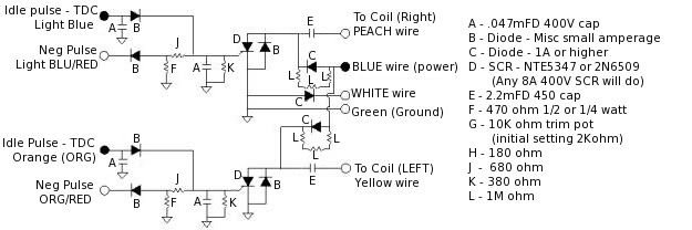
This is a good example of Prototype 1. The input leads (LtBlue/Orange) are coming in from the left and the Blue and White leads are coming in from the right. You can see that there are two SCR's (one for each side). You can also see that the two capacitors/sides have thier own power input from the Blue wire lead. There is a diode that you cannot see located under the top brown capacitor. The two electrolytic capacitors are the 2.2mFD 450V capacitors. To the right are the 'C' diodes....

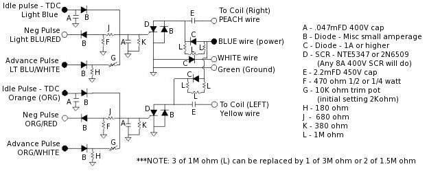
Prototype 2:
- Properties:
- it works
- it's the better of the two
- timing advance
- max revs are same as original
- bike runs well when this iginition is used
- this ignition requires tunning of varistor 'G' to work correctly
There is one thing I would like to change on this schematic when possible. The 'Positive Supply/Blue' should be the same as in Prototype 1. Each capacitor should have it's own diode resistor set without the connection between the two 'L' connectors.

Here is a pcb board for the whole layout...the one on the left is the whole pcb, the one on the right is just the silkscreen for the actual copper layout (so you can print it off and use it as an overlay).


For those wanting to get a general idea of what to expect price wise, here is a list of components I bought to build the CDI boxes...
These prices are really old data from http://www.digikey.com/ and may have changed. You can check all of that out on their online catalog...
| Part # | # | description | Price $US | Totals |
|---|---|---|---|---|
| P5873-ND | 2 | 2.2microF Radial Caps | $0.87 | $1.74 |
| E4473-ND | 6 | .047microF Metal Poly Caps | $0.50 | $3.00 |
| E4153-ND | 2 | .015microF Metal Poly Caps | $0.43 | $0.86 |
| 470QBK-ND | 10 | Resistor 470Ohm 1/4Watt Carbon Film | $0.06 | $0.56 |
| 680QBK-ND | 10 | Resistor 680Ohm 1/4Watt Carbon Film | $0.06 | $0.56 |
| 390QBK-ND | 10 | Resistor 390Ohm 1/4Watt Carbon Film | $0.06 | $0.56 |
| 2.7MH-ND | 5 | Resistor 2.7MOhm 1/2Watt Carbon | $0.06 | $0.27 |
| 1N4004GICT-ND | 20 | Rectifier 1A 400V DO-41 | $0.04 | $0.80 |
| S4008V-ND | 2 | SCR Non-Sensitive Gate 400V 8A TO-251AA | $0.77 | $1.54 |
| 3306P-103-ND | 2 | 10kOhm 6mm RD CERM ST POT | $0.57 | $1.14 |
Total | $11.03 | |||
Handling Charges | $5.00 | |||
Shipping | $4.00 | |||
Total Invoice | $20.03 |
eventually swapped the 10kOhm ceramic pot for a 2kOhm variable resistor. The 10kOhm worked fine, but I wanted to use something smaller.
The wires I used for the prototypes was either 20 or 22 gauge solid wire. In fact that is the wire I have been using through this whole process and it seems to work fine. The connectors I use are the standard automotive type and they work as well.
A PCB kit from your local Radio Shack is about 15.00$US and it has most of what you need. The only other thing you might want to get is a set of Radio Shack's stencils for making the diagram/layout on the PCB. They're realitively cheap and make a MUCH better/cleaner board.
There is also the cost of the soldering iron and solder. If you've never soldered before then you need to search on the internet for some sort of tutorial. There are some out there, that's how I learned...that and practice.
Many thanks to Goerge in NC who wrote this article long time ago. I wonder, does anyone know George current e-mail address, it will be nice if we can discuss about honda CX500 with him.
Note: my PC crash last year and I lost the original schematic files, I apoligize can't send bigger picture anymore.
update:
one of this web visitor give a link for the picture, thank you for RHCE V6.....
RHCE V6 said:
Here are the schematics.
1. this is a very basic circuit that will get you running but has no advance so RPMs are limited to ~6K-7K
http://i1186.photobucket.com/albums/z370/rhcev6/CX500CDI/NO-Advance.jpg

2. this is the full CDI with advance cuircuit. You can set the trip pots initially at 2Kohm and then adjust as needed above 6K RPMs
http://i1186.photobucket.com/albums/z370/rhcev6/CX500CDI/Full-CDI.jpg


32 comments:
Your article is very interesting and I try to build the CDI according to your instructions, but the pictures are not clear enough to see the components value/signs. Can you send me better pictures (schemas)? My e-mail: volker.sauerland(et)gmail.com
ok, no promblem
Your article has really shed light on my effort to get my CX500 on the street. I would really appriciate it though if your could email me clearer images of the diagrams and pictures as they are very hard to read.
Thanks,
Doug Hoffer
Doug,
Can you informed me with your e-mail address? You can send to my e-mail: kelana1967@gmail.com, I'll send you the a better picture/schema.
Hi, this is a Italian CX500 rider, your article is very interesting and I'll try to build the CDI according to your drawing, but the pictures are not clear enough to see the components value/signs. Could you please send me better pictures (schemas)? My e-mail: storm.m@tiscali.it
Thank you in advance.
Mark
Could you send me a clearer image of the diagarm and PC board layout? Thanks Josh
joshthebrain@yahoo.com
Your article is very interesting and I try to build the CDI according to your instructions, but the pictures are not clear enough to see the components value/signs. Can you send me better pictures (schemas)? My e-mail: 14tls15slc@gmail.com
hi i am having problems getting some of the components ie. the src* and the CERM ST POT*. could you possibly give me an equivalent or substitute to these components. they are pretty old and i am unable to find them anywhere
any ideas?
i am having problems finding some of your listed components, ie. (scr non-sensitive gate 400V 8A TO-251AA)* and (10kOhm 6mm RD CERM ST POT)*
if you could send me an updated replacement component that i could find, or a store that supplies them it would be very helpful
any ideas?
thanks-
Hi,
I'm during building DIY-CDI based on PIC but I'm affraid that will have some problems witch it. In that case as backup one I'll try to built yours . Can you please send me better quality schema? e-mail: w.batura (at)op.pl
Thanks in advance!
wbat
Hi I'm from Argentina, and I am restoring a CX 500. but my CDI is burned. seeing your excellent work; comparing the list of components with your diagrams not clear to me where you put the rest. I need your help here do not get anything for my bike and try to make the CDI you designed. Please send me pictures and diagrams to make my e-mail is mohadib2501@hotmail.com. Thank you very much for your time. Fernando López
hi, ur whole site very interesting and useful, my brother will be happy to have his kitcar (cx powered jzr) running again, when i build him ur circuit but would it be possible to email me a clearer schematic thanks pete, my email:peteharvey3@googlemail.com
Hello,
Great thread...I think I need to build my own...could you please send me a clearer schematic for P2?
bonkgr@comcast.net
Hi,
i'm italian so sorry for my bad english..In the schemas i can't read all the value.. Can you send me better pictures?
ospel86@gmail.com
Thanks
Hi, I would like to build this circuit but I also cannot see the details so could you please email me more information.... Yours sincerely Alan
As most of the commentors above, I wonder if i could get a clearer image of the schematics. My Honda cx500 78, have run nicely the last year and taken me through most of Europe, but now stands still due to malfunktion in cdi-unit.
Grateful for reply/
erik@gycklarna.com
I want to thank you for your post. It has opened a new door and hopefully a new life to my CX500.
I have opened my CDI box and I'm in the process of cleaning all the rubber solution and removing the components so, I can possibly have a board duplicated and build a new one. My question is, if it can be done, which I think so, as long as the parts are available. Why not copy the original and get the same rpm's and maybe get another 20 or 30 years out of it.
Thanks again
P.S. I plan to do the same with the rectifier/regulator.
hi superb article but sorry to say the same as everyone else is there any chance that you could send a clearer schematic as the circuit on my brothers kit car has died and he keeps nagging me to build it for him chrs pete
my eimail is peteharvey3@googlemail.com
Alan and Pete, thank you for visiting my blog, however, as I mentioned in my note at the last paragraph, I have lost the original picture due to hard disk problem. But I'm sure I have back up file somewhere. I'll send it to you soon.
Great article. Any luck in locating the clearer schematics? I'd be interested in making my own CDI. Also, how did you remove the rubber from the Honda CDI box. Please e-mail me back at bigragu98@aol.com. Thanks - Larry
Cool web site, I hadn't noticed rajamolor.blogspot.com earlier in my searches!
Continue the excellent work!
Hello,
I have a message for the webmaster/admin here at rajamolor.blogspot.com.
Can I use part of the information from this post above if I provide a backlink back to this site?
Thanks,
Harry
Hi there,
I have a inquiry for the webmaster/admin here at rajamolor.blogspot.com.
Can I use some of the information from this blog post right above if I give a link back to this site?
Thanks,
James
Hello there,
I have a question for the webmaster/admin here at rajamolor.blogspot.com.
May I use some of the information from your post above if I provide a link back to this website?
Thanks,
Oliver
Hello,
Thanks for sharing the link - but unfortunately it seems to be down? Does anybody here at rajamolor.blogspot.com have a mirror or another source?
Thanks,
Oliver
Hey - I am really delighted to discover this. great job!
Can anyone who has gotten a clearer image send a copy to rhcev3@gmail.com please.
My CDI burn out and I am looking to build a replacement as I don't have the $100+ to buy another one.
I built the circuity and the DO workj so I have to thank you for that but I am having a hard time getting the bike to run as well as it used to. I am using 5% resistors and am wondering how exact the resistor values need to be. I am also wondering if you used a timing light to help make resistor adjustments. Do you think replacing resistor K with a 800 Ohm in parallel with a 1K trim pot will help get the timing just right?
Please contact me if you have the time.
Thank you,
Steven Mercurio
RHCEv3 at gmail.com
Here are the schematics.
1. this is a very basic circuit that will get you running but has no advance so RPMs are limited to ~6K-7K
http://i1186.photobucket.com/albums/z370/rhcev6/CX500CDI/NO-Advance.jpg
2. this is the full CDI with advance cuircuit. You can set the trip pots initially at 2Kohm and then adjust as needed above 6K RPMs
http://i1186.photobucket.com/albums/z370/rhcev6/CX500CDI/Full-CDI.jpg
Need your help!! Want to build a cdi but need the better pics and a parts suppler Thank You!
Well I BUILT IT AND IT WORKS! One flaw though the black wire with white stripe is not on the schematic so the bike wont turn off, any suggestions on how to wire it in?
Post a Comment