Ok, lets continue my previous post about the Honda CX500 schematic.
As before, this post refer to old posting by George in NC. He made two CX500 CDI prototypes and I've tried to made the second prototypes and its works!!. I made it twice, the first one was works for more than 3 years and the second one works for one years, its failed at the same time with stator/rotor problem (see my first posting about Honda CX500 by clicking here).
And here what George in NC wrote:
Section II: The Prototypes
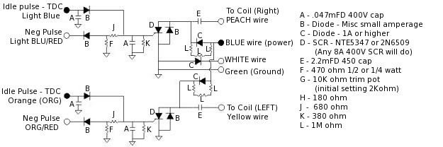
Prototype 1:- Properties:
- it works
- it's the simpler of the two
- no timing advance
- max revs are roughly 6500-7000rpms
- bike runs rich when this iginition is used

This is a good example of Prototype 1. The input leads (LtBlue/Orange) are coming in from the left and the Blue and White leads are coming in from the right. You can see that there are two SCR's (one for each side). You can also see that the two capacitors/sides have thier own power input from the Blue wire lead. There is a diode that you cannot see located under the top brown capacitor. The two electrolytic capacitors are the 2.2mFD 450V capacitors. To the right are the 'C' diodes....

Prototype 2:
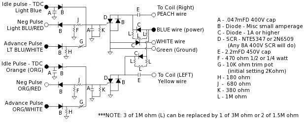
- Properties:
- it works
- it's the better of the two
- timing advance
- max revs are same as original
- bike runs well when this iginition is used
- this ignition requires tunning of varistor 'G' to work correctly
There is one thing I would like to change on this schematic when possible. The 'Positive Supply/Blue' should be the same as in Prototype 1. Each capacitor should have it's own diode resistor set without the connection between the two 'L' connectors.

Here is a pcb board for the whole layout...the one on the left is the whole pcb, the one on the right is just the silkscreen for the actual copper layout (so you can print it off and use it as an overlay).


For those wanting to get a general idea of what to expect price wise, here is a list of components I bought to build the CDI boxes...
These prices are really old data from http://www.digikey.com/ and may have changed. You can check all of that out on their online catalog...
| Part # | # | description | Price $US | Totals |
|---|---|---|---|---|
| P5873-ND | 2 | 2.2microF Radial Caps | $0.87 | $1.74 |
| E4473-ND | 6 | .047microF Metal Poly Caps | $0.50 | $3.00 |
| E4153-ND | 2 | .015microF Metal Poly Caps | $0.43 | $0.86 |
| 470QBK-ND | 10 | Resistor 470Ohm 1/4Watt Carbon Film | $0.06 | $0.56 |
| 680QBK-ND | 10 | Resistor 680Ohm 1/4Watt Carbon Film | $0.06 | $0.56 |
| 390QBK-ND | 10 | Resistor 390Ohm 1/4Watt Carbon Film | $0.06 | $0.56 |
| 2.7MH-ND | 5 | Resistor 2.7MOhm 1/2Watt Carbon | $0.06 | $0.27 |
| 1N4004GICT-ND | 20 | Rectifier 1A 400V DO-41 | $0.04 | $0.80 |
| S4008V-ND | 2 | SCR Non-Sensitive Gate 400V 8A TO-251AA | $0.77 | $1.54 |
| 3306P-103-ND | 2 | 10kOhm 6mm RD CERM ST POT | $0.57 | $1.14 |
Total | $11.03 | |||
Handling Charges | $5.00 | |||
Shipping | $4.00 | |||
Total Invoice | $20.03 |
eventually swapped the 10kOhm ceramic pot for a 2kOhm variable resistor. The 10kOhm worked fine, but I wanted to use something smaller.
The wires I used for the prototypes was either 20 or 22 gauge solid wire. In fact that is the wire I have been using through this whole process and it seems to work fine. The connectors I use are the standard automotive type and they work as well.
A PCB kit from your local Radio Shack is about 15.00$US and it has most of what you need. The only other thing you might want to get is a set of Radio Shack's stencils for making the diagram/layout on the PCB. They're realitively cheap and make a MUCH better/cleaner board.
There is also the cost of the soldering iron and solder. If you've never soldered before then you need to search on the internet for some sort of tutorial. There are some out there, that's how I learned...that and practice.
Many thanks to Goerge in NC who wrote this article long time ago. I wonder, does anyone know George current e-mail address, it will be nice if we can discuss about honda CX500 with him.
Note: my PC crash last year and I lost the original schematic files, I apoligize can't send bigger picture anymore.
update:
one of this web visitor give a link for the picture, thank you for RHCE V6.....
RHCE V6 said:
Here are the schematics.
1. this is a very basic circuit that will get you running but has no advance so RPMs are limited to ~6K-7K
http://i1186.photobucket.com/albums/z370/rhcev6/CX500CDI/NO-Advance.jpg

2. this is the full CDI with advance cuircuit. You can set the trip pots initially at 2Kohm and then adjust as needed above 6K RPMs
http://i1186.photobucket.com/albums/z370/rhcev6/CX500CDI/Full-CDI.jpg

update:
one of this web visitor give a link for the picture, thank you for RHCE V6.....
RHCE V6 said:
Here are the schematics.
1. this is a very basic circuit that will get you running but has no advance so RPMs are limited to ~6K-7K
http://i1186.photobucket.com/albums/z370/rhcev6/CX500CDI/NO-Advance.jpg

2. this is the full CDI with advance cuircuit. You can set the trip pots initially at 2Kohm and then adjust as needed above 6K RPMs
http://i1186.photobucket.com/albums/z370/rhcev6/CX500CDI/Full-CDI.jpg